Submitting clean CAD geometry eliminates back-and-forth engineering revisions and guarantees that every HMI bezel, selector switch, disconnect handle, and conduit gland drops straight into your pre-cut stainless enclosure on arrival. Follow this 7-point Design for Manufacturability (DFM) checklist before releasing DXF or STEP files for N4X-CNC-CUT fiber-laser fabrication.
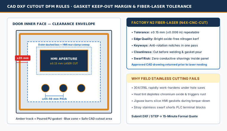
1. Verify Door-Edge Gasket Keep-Out Margins (≥35 mm)
Every NEMA 4X stainless door carries a continuous robot-poured polyurethane gasket track recessed inside its outer folded lip. Placing an HMI or pilot light too close to the edge causes rear bezel mounting clamps to crush the gasket or collide with the body return flange.
- Keep all cutout edges at least 35 mm (1.38 in) inside the outer door perimeter (and 50 mm / 2.0 in on latch-rod or continuous-hinge sides of tall free-standing doors).
- Check the rear bezel clamp sweep, not just the rectangular hole size—most 7-inch to 15-inch HMIs require 18–25 mm of unobstructed flat stainless steel around all four sides of the aperture.
2. Specify Keyway Orientation on 22.5 mm & 30.5 mm Pushbuttons
Fiber lasers cut circular holes and anti-rotation keyways in a single ±0.15 mm pass. In your DXF file:
- Confirm 22.5 mm (IEC) vs. 30.5 mm (NEMA heavy-duty oil-tight) diameters explicitly.
- Orient anti-rotation notches consistently (typically 12 o’clock top dead center) and maintain at least 45–50 mm center-to-center pitch between adjacent pushbuttons so legend plates, contact blocks, and gloved operator fingers never interfere.
3. Check Door-to-Sub-Panel Depth Collision
Before freezing door cutouts, overlay the rear projection depth of your deepest door device (HMI power connector + Ethernet boot + E-stop contact block stack) against the front face of the tallest sub-panel component (PLC power supply, VFD drive, or main circuit breaker). Use our NEMA 4X Sizing Calculator to verify total enclosure depth.
4. Pre-Release CAD Submission Checklist
| Check Item | Required Detail in DXF / STEP / Brief | Why It Prevents Rework |
|---|---|---|
| 1. Units & Scale | 1:1 true scale explicitly marked in mm or inches | Prevents 25.4× metric/imperial scaling errors |
| 2. Viewing Orientation | Label clearly: Viewed from Outside Door Face | Eliminates mirrored left/right HMI & latch layouts |
| 3. Alloy & Gauge | AISI 304 vs. 316L; 16 ga (1.5 mm), 14 ga (2.0 mm), or 12 ga (2.5 mm) | Confirms clamp thickness range for HMI & pushbuttons |
| 4. Device Rating Match | Verify installed HMI/buttons carry Type 4X rating | Preserves completed UL 508A / Type 4X assembly rating |
| 5. Gland Plate Entry | List exact M16–M63 or 1/2”–2” NPT hole diameters | Avoids drilling stainless bottom plates on site |
| 6. Sub-Panel Tapping | Include M4/M5/M6/M8 DIN-rail & duct hole layer if desired | Eliminates manual layout and tapping on panel benches |
| 7. Cooling Cutouts | Supply thermal unit manufacturer DXF for side walls | Ensures sealed NEMA 4X air conditioner gasket contact |
Ready for DFM Verification & 15-Minute Formal Quote
Every enclosure is built to NEMA 250 Type 4X and UL 508A enclosure design requirements; material mill certificates (304/316L) and ingress test reports available per project. Explore full pre-cut capabilities on our CAD Laser Pre-Cut Enclosures hub or upload your cutout list via the 15-Minute Formal Quote Brief.
Standard & Custom-Engineered Models
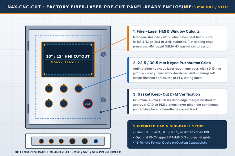
Laser Pre-Cut HMI/Pushbutton Panel-Ready Enclosure
Custom-modified 304 or 316L wall-mount or floor-stand NEMA 4X enclosures with ±0.15 mm CAD fiber-laser HMI, pushbutton, louver/cooler, and gland plate cutouts.
Full Datasheet →